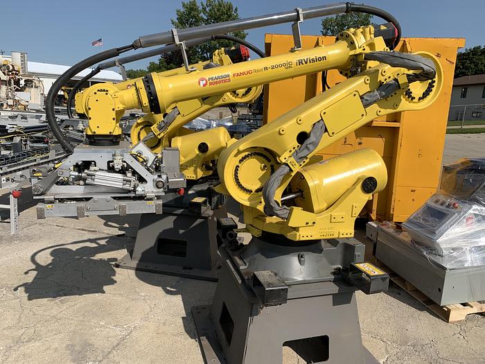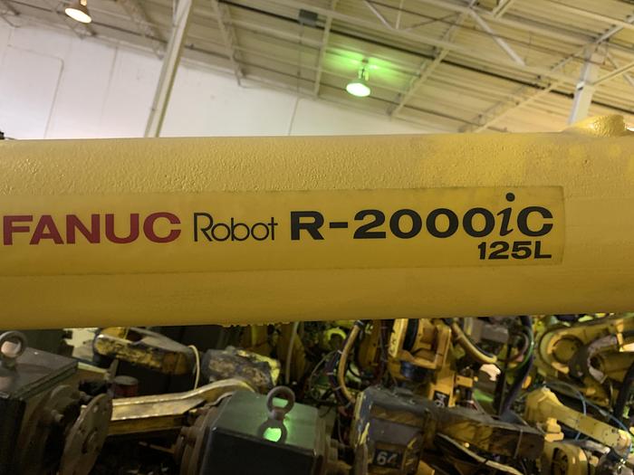
This gripper is used to pick up small parts and other tools such as welding torches and spray guns. The robot also needs a hand or gripper at the end of the arm. Utilizing a robot in a manufacturing setting requires interfacing it with other production equipment, including intake and output conveyors and handling devices. FANUC also has an unguarded option known as the CR-35iA collaborative robot. Task options include high-speed Delta robots and painting robots. Whether it’s a huge machine with long-reach and massive payload capabilities or a compact articulated robot, manufacturing needs can be matched. Through the creation of more than 100 robot models, FANUC has developed robotic technologies to satisfy every task.

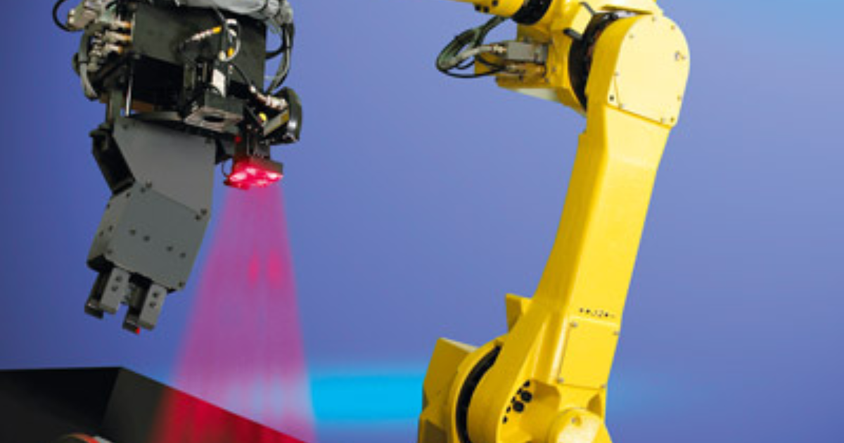
The advanced attributes allow FANUC robots to complete various types of manufacturing tasks. These robots feature state-of-the-art technology including 3D Vision systems for sensing. RG Group understands this complexity and has worked with FANUC to build some of the most sophisticated and productive robots in the world.Īs an automation company, FANUC specializes in creating advanced robotic arms for manufacturing. The complexity of robotic systems requires a thorough understanding of industrial robotics technology and real-world integration experience. Automated robotic systems can provide manufacturing advantages in all industries. Robotic technologies are also necessary when preparing pharmaceuticals in aseptic conditions and to protect workers from dangerous or harmful environments. Robots have the capacity to create products that are too difficult or intricate for human assembly. Throughout the world, FANUC robots are used in factories to improve quality, increase capacity and overcome skills shortages. Robots have forever transformed the way industries develop and manufacture products.

They were placed there to facilitate teaching a robot frame manually with a pointer.Robotics can build your business in ways you never thought possible

The easiest way to check this is to make 2 copies of your grid, place one on top of the other rotated 90 degrees, hold them up to the light, and see if the circles are exactly aligned. We had trouble getting them manufactured accurately at first, as printing equipment tends to have a slight difference in the horizontal and vertical scaling.


 0 kommentar(er)
